Arduino or not Arduino ?
Since 2005, Arduino is very well known by students and DIY fans for his large line of kits implementing ATMEL microcontrollers (mainly but not only) usually used on professional board environments.
The product line is fairly cheap and provides a way to experience the capabilties and functionalities of microcontrollers very quickly as well as thoroughly.
The main benefit is the facilitation of debugging via USB port available on most of the boards. Arduino provides USB CDC class library, in other words a substitute of the famous RS232 port that the Olders as I am, have probably used in the past.
Debugging tools have become much less expansives also because microcontrollers integrate for a while these capabilities (e.g. JTAG), but the cost remains an inappropriate one for students.
In addition to the large range of electronic boards, Arduino also provides to budding-developers, an even more wide software library avoiding to face with the tricky ATMEL Studio: Clock, Timers, USB, I2C, SPI, DAC, GPIO, etc…everything is already implemented and tested – I’ve personaly perfom in ancient times, from-scratch microcontroller initializations while devices were most-less simple. Anyway, I had no choice but to read the hundred of pages of the datasheet and spend hours (sometime days) to just make the board starting.
Fortunatly, this has evolved and for a while now, manufacturers have been provided BSP (Board Support Packages) while a CORTEX M0 RISC-32-bits is quite more complex to initialize compare to an AVR 8-bits.
Thus Arduino library is immensly rich and regulary fed-up by a very large community. I only regret the startup()/loop() approach which is certainly well suit to beginners but ultimately bring them away from reality and so hiding behind the curtains. I would have prefered a main()/while(true) approach..but I confess that this is very snobbish.
ATMEL also provides a very rich software library, but I’ve been particularly disappointed by the development environnement (Studio) – but this remains a personal feeling – since the ASF libraries are not C++ compliante (which was a prerequisite for me, mainly for the code-structured-formalism) and the difficulty of implementation – I’ve also experimented multiple times compilation errors after having only added 1 ot 2 ASF libraries and just after creating a project (no code-lines from my side)
Arduino-‘inspired’ choice is mainly based on a simple fact: I had multiple remaining boards packed into a box (usefull for my first testing). I should also point out that I had not considered developing my own board; two reasons 1) PCB prototypes – 2 layers at least – are horribly expansive 2) assembly – understanding components’ soldering – is greatly complicated by the SMC chips’ pitch.
Why not Raspberry ? just because I don’t like to smash a fly with a hammer…and also for fun ! Measuring humidy&temperature, even though radio support is mandatory, doesn’t need an embedded Linux OS. The Utlimate Rasperry Meeting-room project already gave me the opportuny to have fun with Raspberries.
Microcontroller
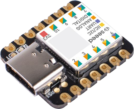 Arduino boards are convenient for testing. But regarding this project, I’ve been particularly attentive to the form-factor and the cost. I knew I was going to need quite a bit of RAM and Flash memories, and the SAMD21 CORTEX M0 + seemed to meet the requirements (e.g. Arduino Zero, MKR WIFI and 33IOT). Also, I started looking for a module based on the same microcontroller, but much smaller and cheaper. I stumbled across the Seeed XIAO from the Chinese brand SEEEDUINO. The number of I/O is obviously limited (because of the small foot-print), but everything I needed is available: USB, UART, I2C and SPI, as well as few GPIOs. Seeeduino XIAO is based on a SAMD21G18A embedding 256kB Flash and 32kB SRAM.
Temperature and Humidity sensor
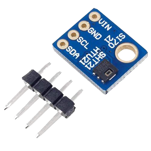 Measures are performed by a very common digital relative humidity sensor with temperature output: HTU21D from TE Connectivity. This sensor reference provides an I2C interface and thanks to few formulas, a way to calculate temperature, relative humidity with temperature compensation, partial pressure and dew point temperature (“point de rosée”). This device is available mounted on multiple tiny modules (e.g.: AZDelivery GY-21).
Radio 868Mhz transceiver
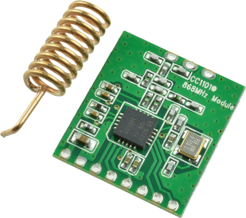 Radio is based on a low-power Sub-1 Ghz RF transceiver from Texas Instrument: CC1101. Thanks to some passive components, the frequency band can be set at 315, 433, 868, and 915Mhz. The common modules are mainly available for both 433 and 868Mhz, and for the reason I’ve explained earlier, I choosed a 868MHZ (e.g. Amazon). The transceiver provides an SPI interface.
To improve the range of the signal, I’ve replaced the small coil-antenna by a real one (e.g. Amazon)
WiFi interface (server/bridge sensor-device only)
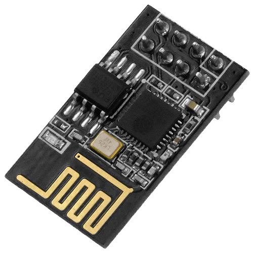 Few options were possible. I choosed the wrong one ! I found out too late that the ESPRESSIF ESP8266 device firmware had been dragging a very ambarrasing bug for more than 5 years. For all this time, the manufacturer has not considered useful to solve the problem. I tried to find out a little bit more by posting questions on the official forum, but my messages remained blocked and were never released by the moderator !
The bug sticks the firmware after a some time, this one depending at the same time on the frequency of the transmissions of message and the quantity; let’s call the “busy p …” bug ! The only solution consists on restarting the module. This is the reason why the reset pin is directly connected to an output of the microcontroller.
The project was too advanced (mainly the driver) in order to consider changing the module at this time.
However it was rather an attractive module because the firmware offers communication via AT commands on a UART bus. It is certainly not very fast, but in any case enough sufficient to post measurement values to a server every 20minutes.
This module consists on an ESP8266, an on-board wifi antenna and provides USART interface (e.g. AZDelivery ESP-01S).
PCB board
 The best way to assemble modules is to use PCB boards for prototyping. On the other hand, even if once connected the modules communicate without any problem, the wiring is very ugly and certainIy not EMC compliant.
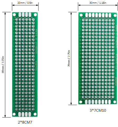
I had an Elegoo kit into a box, so I choosed 2 versions: 70x30mm for the main board and half of a 80x20mm for the temperature&humidity sensor module. The use of 2 differents sizes is just a way to take away the temperature&humidity sensor from the other modules in order to prevent heat dissipation from distorting measurements.
Devices family: server/bridge-sensor
The Server/Bridge sensor is in charge of dispatching all the simple-sensors’ measures (see below) to the API server. The board is full-equiped with all the modules. It also acts as a temperature&humidity sensor. Only a server/bridge-sensor has to be installed per site (let’s say per client).
Devices family: simple-sensor
This board is a sub-equipped version of the server/bridge-sensor, meaning with all the modules excepted the WiFi interface one. Measures are sent to the server/bridge-sendor through the radio-868MHZ. Up-to 127 simple-sensors can be installed on a site. Address 0 is not used and address 255 is reserved for broadcasting. The number of devices depends on the frequency of the measures. In practice, 10 devices is a maximum. I’ve not been able to test more than 5.
1st step: identify modules and components pinouts


Seeed XIAO – top view, main I/Os
Seeed XIAO – bottom view
JTAG signals (optional)


CC1101 transceiver
ESP-01S


HTU21D humidity&Temperature sensor module
Reset push-button


Optional JTAG header
Jumper (forcing measurement)
2nd step: modules and component assembly
Simply connect the modules between them by refering to the pinouts and labels. Consider only the labels and not the colors. I’ve deliberately moved away the sensor from other modules in order to avoid the measures beiing distorded by heat release.

Top view – modules and components positionning

bottom (or spaghetti) view
Points of attention
- JTAG header is optional. It requires a dedicated device, e.g.: SEGGER JLINK EDU which can be found between 10€ to 20€. I’ve got one in order to speed-up binaries downolading during development and also performing debugging especially thanks to breakpoints.
- Jumper header is mapped in order to perform or force an immediate temperature&humidy measure and transmission to the API, without waiting for the timer expiration (typicaly 20mn, but can be set from 1 to 1440 minutes by the settings tool).
- ESP-01S module (WiFi interface) is only mounted on the server/bridge-sensor device.
Now, let’s dive into the devices software…